Introduction to devicetree
Tip
This is a conceptual overview of devicetree and how the Cogeno EDTS database module provides the devicetree information.
A devicetree is a hierarchical data structure that describes hardware. The Devicetree specification defines its source and binary representations. Devicetree may be used to describe the hardware available on a board, as well as that hardware’s initial configuration.
There are two types of devicetree input files: devicetree sources and devicetree bindings. The sources contain the devicetree itself. The bindings describe its contents, including data types. The EDTS database module uses devicetree sources and bindings to produce a key-value database, which you can use to get information from your devicetree. The keys are pathes to the device tree information.
Here is a view of the process executed by the EDTS database module:

EDTS database build flow
All Cogeno script snippets can access the EDTS database.
/* This is my C file. */
...
/**
 * @code{.cogeno.py}
 * edtsdb = cogeno.edts()
 * ...
 * @endcode{.cogeno.py}
 */
/** @code{.cogeno.ins}@endcode */
...
Syntax and structure
As the name indicates, a devicetree is a tree. The human-readable text format for this tree is called DTS (for devicetree source), and is defined in the Devicetree specification.
Here is an example DTS file:
/dts-v1/;

/ {
        a-node {
                subnode_label: a-sub-node {
                        foo = <3>;
                };
        };
};
The /dts-v1/; line means the file’s contents are in version 1 of the DTS
syntax, which has replaced a now-obsolete “version 0”.
The tree has three nodes:
A root node:
/A node named
a-node, which is a child of the root nodeA node named
a-sub-node, which is a child ofa-node
Nodes can be given labels, which are unique shorthands that can be used to
refer to the labeled node elsewhere in the devicetree. Above, a-sub-node
has label subnode_label. A node can have zero, one, or multiple node
labels.
Devicetree nodes have paths identifying their locations in the tree. Like
Unix file system paths, devicetree paths are strings separated by slashes
(/), and the root node’s path is a single slash: /. Otherwise, each
node’s path is formed by concatenating the node’s ancestors’ names with the
node’s own name, separated by slashes. For example, the full path to
a-sub-node is /a-node/a-sub-node.
Devicetree nodes can also have properties. Properties are name/value pairs. Property values can be any sequence of bytes. In some cases, the values are an array of what are called cells. A cell is just a 32-bit unsigned integer.
Node a-sub-node has a property named foo, whose value is a cell with
value 3. The size and type of foo’s value are implied by the enclosing
angle brackets (< and >) in the DTS. See
Writing property values below for more example property values.
In practice, devicetree nodes usually correspond to some hardware, and the node hierarchy reflects the hardware’s physical layout. For example, let’s consider a board with three I2C peripherals connected to an I2C bus controller on an SoC, like this:
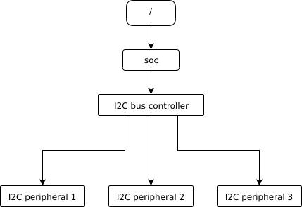
Nodes corresponding to the I2C bus controller and each I2C peripheral would be present in the devicetree. Reflecting the hardware layout, the I2C peripheral nodes would be children of the bus controller node. Similar conventions exist for representing other types of hardware.
The DTS would look something like this:
/dts-v1/;

/ {
        soc {
                i2c-bus-controller {
                        i2c-peripheral-1 {
                        };
                        i2c-peripheral-2 {
                        };
                        i2c-peripheral-3 {
                        };
                };
        };
};
Properties are used in practice to describe or configure the hardware the node represents. For example, an I2C peripheral’s node has a property whose value is the peripheral’s address on the bus.
Here’s a tree representing the same example, but with real-world node names and properties you might see when working with I2C devices.

I2C devicetree example with real-world names and properties. Node names are at the top of each node with a gray background. Properties are shown as “name=value” lines.
This is the corresponding DTS:
/dts-v1/;

/ {
        soc {
                i2c@40003000 {
                        compatible = "nordic,nrf-twim";
                        label = "I2C_0";
                        reg = <0x40003000 0x1000>;

                        apds9960@39 {
                                compatible = "avago,apds9960";
                                label = "APDS9960";
                                reg = <0x39>;
                        };
                        ti_hdc@43 {
                                compatible = "ti,hdc", "ti,hdc1010";
                                label = "HDC1010";
                                reg = <0x43>;
                        };
                        mma8652fc@1d {
                                compatible = "nxp,fxos8700", "nxp,mma8652fc";
                                label = "MMA8652FC";
                                reg = <0x1d>;
                        };
                };
        };
};
In addition to showing more realistic names and properties, the above example
introduces a new devicetree concept: unit addresses. Unit addresses are the
parts of node names after an “at” sign (@), like 40003000 in
i2c@40003000, or 39 in apds9960@39. Unit addresses are optional:
the soc node does not have one.
Some more details about unit addresses and important properties follow.
Unit address examples
In devicetree, unit addresses give a node’s address in the address space of its parent node. Here are some example unit addresses for different types of hardware.
- Memory-mapped peripherals
The peripheral’s register map base address. For example, the node named
i2c@40003000represents an I2C controller whose register map base address is 0x40003000.- I2C peripherals
The peripheral’s address on the I2C bus. For example, the child node
apds9960@39of the I2C controller in the previous section has I2C address 0x39.- SPI peripherals
An index representing the peripheral’s chip select line number. (If there is no chip select line, 0 is used.)
- Memory
The physical start address. For example, a node named
memory@2000000represents RAM starting at physical address 0x2000000.- Memory-mapped flash
Like RAM, the physical start address. For example, a node named
flash@8000000represents a flash device whose physical start address is 0x8000000.- Fixed flash partitions
This applies when the devicetree is used to store a flash partition table. The unit address is the partition’s start offset within the flash memory. For example, take this flash device and its partitions:
flash@8000000 {
    /* ... */
    partitions {
            partition@0 { /* ... */ };
            partition@20000 {  /* ... */ };
            /* ... */
    };
};
The node named
partition@0has offset 0 from the start of its flash device, so its base address is 0x8000000. Similarly, the base address of the node namedpartition@20000is 0x8020000.
Important properties
Some important properties are:
- compatible
The name of the hardware device the node represents.
The recommended format is
"vendor,device", like"avago,apds9960", or a sequence of these, like"ti,hdc", "ti,hdc1010". Thevendorpart is an abbreviated name of the vendor. The file :zephyr_file:`dts/bindings/vendor-prefixes.txt` contains a list of commonly acceptedvendornames. Thedevicepart is usually taken from the datasheet.It is also sometimes a value like
gpio-keys,mmio-sram, orfixed-clockwhen the hardware’s behavior is generic.The build system uses the compatible property to find the right bindings for the node. Device drivers use
devicetree.hto find nodes with relevant compatibles, in order to determine the available hardware to manage.The
compatibleproperty can have multiple values. Additional values are useful when the device is a specific instance of a more general family, to allow the system to match from most- to least-specific device drivers.Within Zephyr’s bindings syntax, this property has type
string-array.- label
The device’s name according to Zephyr’s device_model_api. The value can be passed to
device_get_binding()to retrieve the corresponding driver-level struct device*. This pointer can then be passed to the correct driver API by application code to interact with the device. For example, callingdevice_get_binding("I2C_0")would return a pointer to a device structure which could be passed to I2C API functions likei2c_transfer(). The generated C header will also contain a macro which expands to this string.- reg
Information used to address the device. The value is specific to the device (i.e. is different depending on the compatible property).
The
regproperty is a sequence of(address, length)pairs. Each pair is called a “register block”. Here are some common patterns:Devices accessed via memory-mapped I/O registers (like
i2c@40003000):addressis usually the base address of the I/O register space, andlengthis the number of bytes occupied by the registers.I2C devices (like
apds9960@39and its siblings):addressis a slave address on the I2C bus. There is nolengthvalue.SPI devices:
addressis a chip select line number; there is nolength.
You may notice some similarities between the
regproperty and common unit addresses described above. This is not a coincidence. Theregproperty can be seen as a more detailed view of the addressable resources within a device than its unit address.- status
A string which describes whether the node is enabled.
The devicetree specification allows this property to have values
"okay","disabled","reserved","fail", and"fail-sss". Only the values"okay"and"disabled"are currently relevant to Zephyr; use of other values currently results in undefined behavior.A node is considered enabled if its status property is either
"okay"or not defined (i.e. does not exist in the devicetree source). Nodes with status"disabled"are explicitly disabled. (For backwards compatibility, the value"ok"is treated the same as"okay", but this usage is deprecated.) Devicetree nodes which correspond to physical devices must be enabled for the correspondingstruct devicein the Zephyr driver model to be allocated and initialized.- interrupts
Information about interrupts generated by the device, encoded as an array of one or more interrupt specifiers. Each interrupt specifier has some number of cells. See section 2.4, Interrupts and Interrupt Mapping, in the Devicetree Specification release v0.3 for more details.
Zephyr’s devicetree bindings language lets you give a name to each cell in an interrupt specifier.
Aliases and chosen nodes
There are two additional ways beyond node labels to refer to a particular node without specifying its entire path: by alias, or by chosen node.
Here is an example devicetree which uses both:
/dts-v1/;

/ {
     chosen {
             zephyr,console = &uart0;
     };

     aliases {
             my-uart = &uart0;
     };

     soc {
             uart0: serial@12340000 {
                     ...
             };
     };
};
The /aliases and /chosen nodes do not refer to an actual hardware
device. Their purpose is to specify other nodes in the devicetree.
Above, my-uart is an alias for the node with path /soc/serial@12340000.
Using its node label uart0, the same node is set as the value of the chosen
zephyr,console node.
Zephyr sample applications sometimes use aliases to allow overriding the
particular hardware device used by the application in a generic way. For
example, blinky-sample uses this to abstract the LED to blink via the
led0 alias.
The /chosen node’s properties are used to configure system- or
subsystem-wide values. See devicetree-chosen-nodes for more information.
Input and output files
This section describes the input and output files shown in the figure at the top of this introduction in more detail.
Input files
There are three basic types of devicetree input files:
sources (
.dts)includes (
.dtsi)bindings (
.yaml)
As the devicetree files are preprocessed by the C/C++ style preprocessor any includes may de done.
includes (
.h, …)
Usually every board has a <board>.dts file describing its hardware.
<board>.dts includes one or more .dtsi files. These .dtsi files
describe the CPU or system-on-chip the board is made of, perhaps by including other
.dtsi files. They can also describe other common hardware features shared by
multiple boards. In addition to these includes, <board>.dts also describes
the board’s specific hardware.
The C/C++ style preprocessor is run on all
devicetree files to expand macro references, and includes should generally be done
with #include <filename> directives, even though DTS has a
/include/ "<filename>" syntax.
Some project build systems may support to extend and/ or modify the <board>.dts
by using overlays. Overlays are also DTS files; The build system concatenates the
overlay files to the <board>.dts, with the overlays put last. This relies
on DTS syntax which allows merging overlapping definitions of nodes in the devicetree.
Devicetree bindings (which are YAML files) are essentially glue. They describe the contents of devicetree sources, includes, and overlays in a way that allows to extract the EDTS database usable by Cogeno scripts. The EDTS database module provides a set of generic bindings.
Output files
edts.dtsThe final merged devicetree. This file is output by the EDTS database module as a debugging aid, and is unused otherwise.
edts.jsonThe EDTS database as a .json export. This file, if available, is read in by the EDTS database module to avoid multiple evaluation of the devicetree. Dependency changes are regarded and lead to a full re-evaluation.
Writing property values
Here are some example ways to write property values in DTS format. Some specifics are skipped in the interest of keeping things simple; if you’re curious about details, see the devicetree specification.
Arrays of 32-bit unsigned integers, or cells, can be written between angle
brackets (< and >) and separated by spaces:
foo = <0xdeadbeef 1234 0>;
The foo property value is three cells with values 0xdeadbeef, 1234, and 0,
in that order. Note that hexadecimal and decimal numbers are allowed and can be
intermixed. Since Zephyr transforms DTS to C sources, it is not necessary to
specify the endianness of an individual cell here.
64-bit integers are written as two 32-bit cells in big-endian order. The value
0xaaaa0000bbbb1111 would be written <0xaaaa0000 0xbbbb1111>.
Parentheses, arithmetic operators, and bitwise operators are allowed. The
bar property contains a single cell with value 64:
bar = <2 * (1 << 5)>;
Strings are double quoted:
a-string = "hello, world!";
String arrays are separated by commas:
a-string-array = "string one", "string two", "string three";
Arrays of bytes are written in hexadecimal without leading 0x between
square brackets ([ and ]). Property a-byte-array is the three bytes
0x00, 0x01, 0xab, in that order:
a-byte-array = [00 01 ab];
Properties can refer to other nodes in the devicetree by their phandles. You
can write a phandle using &label, like in this devicetree fragment:
baz: device@0 {
        /* ... */
};
device@1 {
        sibling = <&baz 1 2>;
        /* ... */
};
The sibling property of node device@1 contains three cells:
The
device@0node’s phandle. Each phandle occupies an entire cell. Thebazlabel is used to write the phandle&bazinside thesiblingproperty value.The values 1 and 2, each in its own cell, in that order.